NEW DEMO
The Curved Cube
To get a feel for this demo try this. Take a solid cube with rods attached at diagonally opposite vertices. (See Figure 1.) Hold the rods horizontally and rapidly spin the cube. You should see a curved outline formed by the spinning cube. Our objective is to discover how the straight edges of the cube trace a curve using the vertices as the cube spins. In addition, a formula for the curve will be developed, displayed step-by-step, and geometric features are supplied. In order to show the images of the rotation of the cube a program was used.
 Figure 1.
|
|
Background and Math Tools
|
For the one instant in time shown in Figure 1 the upper outline is simply three lines which we outlined in Figure 2, but as the cube is rotated that outline changes. What we see as the cube is quickly rotated is the points on the edge of the cube when they appear to be at a maximum distance from the center of rotation.
 Figure 2.
|
A simulation of this behavior can be generated by using a Styrofoam cube with a nail inserted in a corner. Next, insert the nail in the chuck of a variable speed drill, tighten the drill chuck, and experiment with drill speeds to generate a view of the behavior of the points on the edges of the cube as described above. See Figure 3.
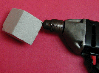 Figure 3.
|
The two animations below simulate the action of the cube spinning in the drill. These animations were constructed in MATLAB. In both animations you can see an arc that appears at the top and bottom. This is much easier to see in the "slower" image.
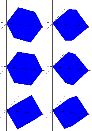 Rotating Cube 3D. |
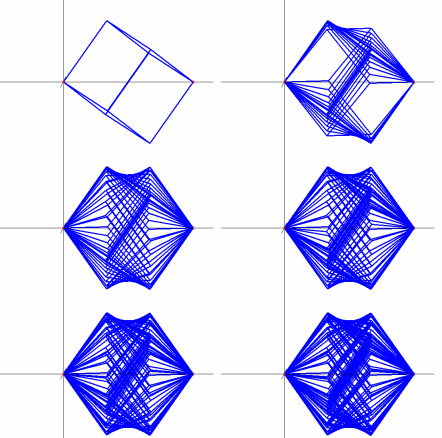 Slow Cube Faces 2D. |
The Mathematical Model
To determine the equations for the visual outline of the spinning cube we assume that the edge of the cube is one unit with point O at the origin (0, 0, 0) and point P at (1, 1, 1). The line segment OP is the axis of revolution and point A is (0, 0, 1) with B at (0, 1, 1) as shown in Figure 4.
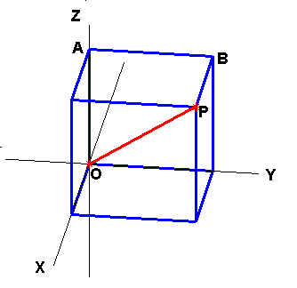
Figure 4. |
As the cube is quickly rotated the points we see there are the points on the edge of the cube when they appear at a maximum distance from the center of rotation. This means that to determine the shape of the outline of the rotating cube we need to compute the distance from each point on an edge to the axis of revolution segment OP. For a point (x, y, z) on an edge consider the plane containing it and the points O and P. We define the independent variable t to be the distance from the origin O to a point along the axis of revolution. That is,t = 0 corresponds to the origin and t increases as we move along the axis of rotation towards P. The distance formula for point in 3-space tells us that at P we have \(t = \sqrt{3}\) . Our task is to compute the height h as a function of t for each point on an edge of the cube. (See Figure 5.) The graph of h(t) for \(0 \leq t \leq \sqrt{3}\) shows the visual outline of the spinning cube.
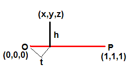
Figure 5. |
Since each edge of our cube lies in a coordinate plane or in a plane parallel to a coordinate plane only one of x, y, or z varies along an edge. Hence we need only consider three representative edges; one in which each of x, y, or z varies. We will use the three edges OA, AB, and BP shown in Figure 4.
Edge OA
The z-coordinate varies along OA, and any point Q along it has coordinates (0, 0 , z) for some z between 0 and 1. To find h as a function of t for point Q we first compute the length of the projection (also called the scalar projection) of the vector \(\overrightarrow{OQ}\) onto vector \(\overrightarrow{OP}\). (See Figure 6.) This length is the value of t corresponding to the projection of \(\overrightarrow{OQ}\) onto \(\overrightarrow{OP}\) and then the height associated with point Q is determined by the Pythagorean Theorem.
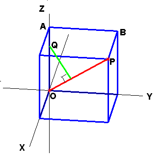
Figure 6. |
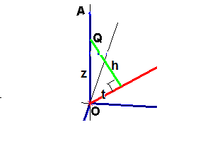
Figure 7. |
and \(t^2 + h^2 = z^2\) as seen from Figure 7. Using the value of t and solving for h we have \(h = t\sqrt{2}\). Along edge OA z extends from 0 to 1 so \(0 \leq z \leq 1\), then using \(z = \sqrt{3}\,t\) we have that \(0 \leq t \leq \frac{1}{\sqrt{3}}\) so t ranges from 0 to \(\frac{1}{\sqrt{3}}\). This gives a portion of the description of h as a function of t as shown below.
\[h(t) = \begin{cases} t\,\sqrt{2}, & \text{for} \; 0 \leq t \leq \frac{1}{3}\sqrt{3} \\[2ex] \qquad \text{?} \\ \end{cases} \]Edge PB
The x-coordinate varies along PB, and any point Q along it has coordinates (x, 1 , 1) for some x between 0 and 1. Again the task is to find h as a function of t for point Q. Here the right side of OP is used (see Figure 5), so it is convenient to orient all vectors from right to left. Hence t will be measured from P so we seek the value of \(\sqrt{3} - t\). Thus we determine the length of the projection of QP onto PO as \[\sqrt{3} - t = \frac{[x-1\;0\;0]\cdot [-1\;-1\;-1]}{\Vert{[-1\;-1\;-1]}\Vert} = \frac{1-x}{\sqrt{3}}\]
It follows again from the Pythagorean Theorem (see Figure 8) that
\[(\sqrt{3} - t)^2 + h^2 = (1 - x)^2\]and so using \(\sqrt{3} - t = \frac{1-x}{\sqrt{3}}\) we can solve for h to get
\[h =\sqrt{ (1 - x)^2 - (\sqrt{3} - t)^2} = \sqrt{2} \; (\sqrt{3} -t).\]This side extends from x = 0 to x = 1, so t ranges from \(\frac{2}{3}\sqrt{3}\) to \(\sqrt{3}\). Thus we can describe the function h(t) in the form
\[h(t) = \begin{cases} t\,\sqrt{2}, & \text{for} \; 0 \leq t \leq \frac{1}{3}\sqrt{3} \\[2ex] \qquad \text{?} \\ \sqrt{2}(3 - t), & \text{for} \; \frac{2}{3}\sqrt{3} \leq t \leq \sqrt{3} \\ \end{cases}. \]
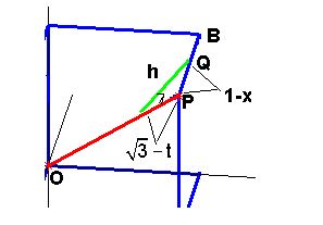
Figure 8. |
Edge AB
The y-coordinate varies along AB, and any point Q along it has coordinates (0, y , 1) for some y between 0 and 1. Following a procedure similar to that for edge OA, we have
\[ t = \frac{[0\;y\;1]\cdot [1\;1\;1]}{\Vert{[1\;1\;1]}\Vert} = \frac{y+1}{3}.\]The hypotenuse of the triangle in this case is \(\sqrt{y^2 + 1}\) (see Figure 9) hence we have \(t^2 + h^2 = y^2 + 1\). Substituting for y in terms of t and solving for h gives
\[h=\sqrt{y^2 + 1 - t^2} = \sqrt{2t^2 - 2\sqrt{3}\,t + 2}\]
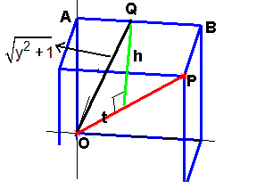
Figure 9. |
Thus the formula that describes the height as function of t is
\[h(t) = \begin{cases} t\,\sqrt{2}, & \text{for} \; 0 \leq t \leq \frac{1}{3}\sqrt{3} \\[2ex] \sqrt{2t^2 - 2\sqrt{3} \, t + 2} , & \text{for} \; \frac{1}{3} \sqrt{3} \leq t \leq \frac{2}{3}\sqrt{3} \\ \sqrt{2}(3 - t), & \text{for} \; \frac{2}{3}\sqrt{3} \leq t \leq \sqrt{3} \\ \end{cases} \]It turns out that the remaining edges of the cube only produce copies of the expressions in h(t).
The Curve of the Cube
A graph of the function h(t) is shown in Figure 10. As you can see from watching the rotating cube, the outline is straight on the sides and curved in the middle.
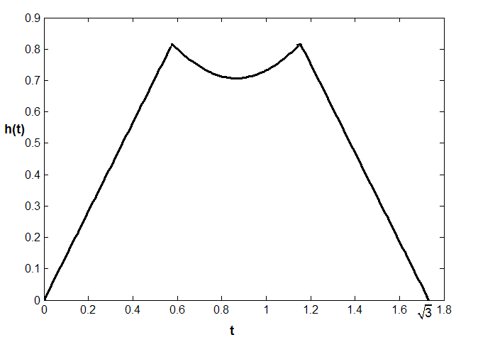
Figure 10. |
More can be said about the curved portion of h(t). Let
\[m(t) = \sqrt{2t^2 - 2\sqrt{3}\,t + 2}\]then squaring both sides and rearranging terms we get
\[m^2 - 2(t^2 - \sqrt{3}\,t) = 2\]and completing the square in t we obtain the expression
\[m^2 - 2(t - \frac{1}{2}\sqrt{3})^2 = \frac{1}{2}\]which is the equation of a hyperbola. Thus the curved shape seen when the cube is rapidly rotated is actually a portion of a hyperbola.
With Linear Algebra
In a linear algebra course this demo provides an opportunity to employ topics that are often described as elementary computer graphics. In the development of the function h(t) we used a unit cube with its lower left back corner at the origin O of a three dimensional coordinate system and viewed the axis of revolution as the segment OP as in Figure 4. However, when we illustrated the spinning cube in the animation at the beginning of the demo and discussed the rotations of the cube as in Figures 1 and 2 we changed the orientation of the cube so that segment OP appeared horizontal. Certainly this eases the use of a physical model and would be a natural position for using the drill in Figure 3. This change of view can initiate a discussion about how to rotate the cube of Figure 4 to that in Figure 1. Once this is done a further discussion of how to achieve the spinning effect naturally follows. Each of these involve rotations about coordinate axes in 3-space and parameterizing rotations to perform a spin. Ideally it would be nice for students to perform the steps in a programming language or in a mathematical environment like Maplesoft, Mathematica, MATLAB, etc. This could be used as a group project for an appropriate class. Following is an animation of the process which emphasizes the requisite steps. (The animation is deliberately slow to show steps.) This animation was developed in MATLAB.
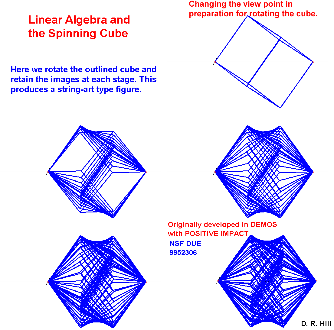
Figure 11. |
It is difficult to see the cubes falling on top of one another. For a view of just several click this thumbnail
![]() .
.
Credits:
- This demo is a modification of a demo in the project Demos with Positive Impact , National Science Foundation's Course, Curriculum, and Laboratory Improvement Program under grant DUE 9952306. managed by David R. Hill and Lila Roberts. The project was based on submitted ideas from instructors. This demo was suggested by Dr. Richard Grant and submitted by Dr. Roland Minton both of Roanoke College, Salem Virginia, and is included in Demos with Positive Impact with their permission. The animations and figures were created in MATLAB by David R. Hill and included with his permission. The MATLAB programs are available by contacting us.