Auxiliary Support
Curved Cube: Definitions & Tools
Easy Jumps to Topics
Vectors
Notations for Vectors
Basic Operations on Vectors
Dot Product of Vectors
Projection
Sources
===============================
Directed Line Segments and Vectors
Lets start with points. Points in a plane or 2D are coordinate ordered pairs like \((x_1, y_1)\). Points in 3 space or 3D have 3 ordered coordinates like \((x_1, y_1, z_1)\).
A line segment is a straight line that is bounded by two distinct end points, and contains every point on the line that is between its endpoints.
To see a 2D line segment click this thumbnail
![]() .
To see a 3D line segment click this thumbnail
.
To see a 3D line segment click this thumbnail
![]() .
.
Next consider vectors. In mathematics and STEM areas, a line segment that has length (or magnitude) and direction is called a (geometric) vector.
Notation used for a vector often uses an arrow or letter in bold face, but there are other techniques used.
Click this thumbnail
![]() for examples. The starting point of a vector is called the initial point while the end is called the terminal point. In Figure 1 we labeled them A and B. From the grid in Figure 1
we see that A has coordinates (-3, -2) and B is (3, 3). As we move from A to B we follow a transition in the grid 6 units horizontally and 4 units vertical as illustrated in Figure 2.
This transition provides a way to view a vector in a simple way that lets us "copy" it at any starting point in the grid. So we can say \(\overrightarrow{AB} = (6, 4)\). EXERCISE:
Determine the vector equation for each vector in Figure 3; use the transition procedure. To check your answers click this thumbnail
for examples. The starting point of a vector is called the initial point while the end is called the terminal point. In Figure 1 we labeled them A and B. From the grid in Figure 1
we see that A has coordinates (-3, -2) and B is (3, 3). As we move from A to B we follow a transition in the grid 6 units horizontally and 4 units vertical as illustrated in Figure 2.
This transition provides a way to view a vector in a simple way that lets us "copy" it at any starting point in the grid. So we can say \(\overrightarrow{AB} = (6, 4)\). EXERCISE:
Determine the vector equation for each vector in Figure 3; use the transition procedure. To check your answers click this thumbnail
![]() .
.

Figure 1. |

Figure 2. |

Figure 3. |
The length of a line segment or a vector is computed using the coordinates of the end point. This is the same as the distance between the end points. For a pair of points in a plane, \( (x_1, y_1) \) and \( (x_2, y_2) \), the distance between the points is computed from the formula \[d = \sqrt{ (x_2 - x_1)^2 + (y_2 - y_1)^2}\] For a pair of points in 3D, \((x_1, y_1, z_1)\) and \((x_2, y_2, z_2)\), get the distance between the points using the formula \[d = \sqrt{ (x_2 - x_1)^2 + (y_2 - y_1)^2 + (z_2 - z_1)^2}\]
Two examples are displayed next.

Figure 4. |

Figure 5. |
The orientation of the 3D figure makes it difficult to read the coordinates of the points. However, since this figure was generated by MATLAB we can change the view.
Here are three thumbnails to see other orientations: click them in any order.
![]()
![]()
![]()
Notations for Vectors
There are various notations for vectors. For example, if your vector is labeled v it might be in bold face print like v or it can be v with an arrow on top like \(v^\to\) or \(\vec{v}\) . Often capital letters are used for naming vectors so you might see \(\vec{V}\). A line segment in which you have named the points (usually capital letters) say A and B, then the symbol is used for the name of the vector, like \(\overrightarrow{AB} \) (which we used previously). Another alternative is to use a bar over the vector name like \(\bar{V}\).
The length (magnitude) of a vector V is of expressed between double vertical bars like \(\Vert{V}\Vert\). Similarly the length of vector \(\overrightarrow{AB}\) is \(\Vert{\overrightarrow{AB}}\Vert\). Some times single vertical bars are used like \(\vert{\overrightarrow{AB}}\vert\).
Basic Operations on Vectors
We will restrict our attention to vectors in 2D and 3D. Most linear algebra texts provide attention beyond these two cases which behave in a corresponding way.
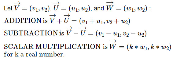
Two major operations are addition (which includes subtraction) and multiplication by a scalar (for us a real number).
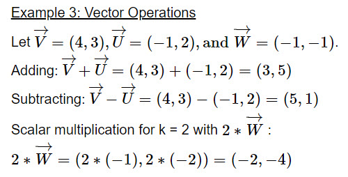
Adding two vectors require that they are both in 2D or both in 3D. Here we use the vector in transition form as discussed above.
|
|
The definitions above are algebraic operations on vectors. However, there are corresponding geometric operations that provide the same results. We illustrate the geometric operations of the same vectors that were used in Example 3. Since we use the transition form for the vectors we can choose the initial point to start our geometric steps. We chose the point (-3, -2). to sketch vector \(\overrightarrow{V}\) and (0, 0) for the scalar multiplication of \(\overrightarrow{W}\).
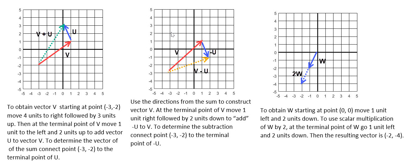
Figure 6. |
Dot Product of Vectors
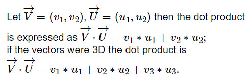
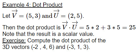
There are a number of different operations on vectors. Above we discussed scalar multiples on a vector. There are other types of multiplication that are used to get more information between a pair of vectors. For our purposes we will focus on a dot product of two vectors which result in a scalar value (an ordinary number). All vectors are used in the transition form.
|
|
The dot product also has geometric connections. For instance, the length of a vector is equal to the square root of the dot product of the vector itself; that is for 2D \(\Vert{\overrightarrow{V}}\Vert = \sqrt{ \overrightarrow{V} \cdot \overrightarrow{U}}= \sqrt{v_1^2 + v_2^2}\). A corresponding expression in 3D is also valid.
An equivalent definition is
\(\overrightarrow{V} \cdot \overrightarrow{U} = \Vert{\overrightarrow{V}}\Vert\) \(\Vert{\overrightarrow{V}}\Vert \cdot cos(\theta)\)
where \(\theta\) is the angle between the two vectors; click this thumbnail
![]() .
It follows that \(cos(\theta) = \frac{\overrightarrow{V} \cdot \overrightarrow{U}}{ \Vert{\overrightarrow{V}}\Vert \Vert{\overrightarrow{U}}\Vert }\). Intuitively, the dot product
tells us something about how much two vectors point in the same direction. (Most linear algebra texts show the
details on this equivalence using the "law of cosines" and properties of dot products. See
Law of Cosines.)
The angle between the vectors in the thumbnail is \(0^\circ \leq \theta \leq 180^\circ\).
Thus, \(cos(\theta) = 0\) if and only if \(\theta =90^\circ\) so the dot product of two nonzero vectors in 2D (or 3D) in this case must be a right angle.
The term orthogonal is used to describe such vectors.
.
It follows that \(cos(\theta) = \frac{\overrightarrow{V} \cdot \overrightarrow{U}}{ \Vert{\overrightarrow{V}}\Vert \Vert{\overrightarrow{U}}\Vert }\). Intuitively, the dot product
tells us something about how much two vectors point in the same direction. (Most linear algebra texts show the
details on this equivalence using the "law of cosines" and properties of dot products. See
Law of Cosines.)
The angle between the vectors in the thumbnail is \(0^\circ \leq \theta \leq 180^\circ\).
Thus, \(cos(\theta) = 0\) if and only if \(\theta =90^\circ\) so the dot product of two nonzero vectors in 2D (or 3D) in this case must be a right angle.
The term orthogonal is used to describe such vectors.
Projection
Basically a projection is the shadow cast by an object. Here we consider a projection of one vector onto another vector. At the terminal end of one vector we drop a line that will be perpendicular to the other vector. (We may need to extend that other vector to complete the right triangle.) See the Figure 7 which shows the geometric point of view.
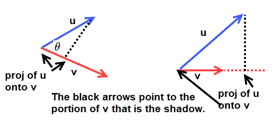
Figure 7. |
The pictures in Figure 7 indicate that the projection of vector u on to vector v is in the same direction as v
and by using trigonometry the length of the projection is \(cos(\theta) \Vert{\mathbf{u}}\Vert\). Click this thumbnail
![]() to see why.
to see why.
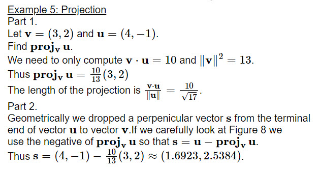
The projection of vector u onto vector v has a length as discussed above, but we can also view it as a vector. We adopt the following notation for this vector \[\mathbf{proj_v}\,\mathbf{u}\]
Next we use a bit of algebra to get a formula for the vector \(\mathbf{proj_v}\,\mathbf{u}\). The length of the projection is \(cos(\theta) \Vert{\mathbf{u}}\Vert\) and from Figure 7 we see that the projection of vector u onto vector v is in the same direction as vector v. Thus algebraically we can express the projection as its length times a vector of length 1 (also called a unit vector) which has the same direction as v. This vector is \(\frac{\mathbf{v}} {\Vert{\mathbf{v}}\Vert}\). Hence we have the expression \[\mathbf{proj_v}\,\mathbf{u} = cos(\theta) \Vert{\mathbf{u}}\Vert \, \frac{\mathbf{v}} {\Vert{\mathbf{v}}\Vert}\]
We can get another expression for the projection vector by using some results that appear in most linear algebra texts. For simplicity we will not show the details in obtaining the following expression for the \(cos(\theta)\). (If you want to see the details click Details.)
\[cos(\theta) = \frac{\mathbf{v} \cdot \mathbf{u} } {\Vert{\mathbf{v}}\Vert \, \Vert{\mathbf{u}}\Vert }\]Using this expression for the cosine we have another formula for the projection vector, \[\mathbf{proj_v}\,\mathbf{u} = \frac{\mathbf{v} \cdot \mathbf{u} } {\Vert{\mathbf{v}}\Vert \,\Vert{\mathbf{u}}\Vert } \Vert{\mathbf{u}}\Vert \, \frac{\mathbf{v}} {\Vert{\mathbf{v}}\Vert}\] and simplifying we get \[\mathbf{proj_v}\,\mathbf{u} = \frac{\mathbf{v} \cdot \mathbf{u} } {\Vert{\mathbf{v}}\Vert^2} \, \mathbf{v} \]
|
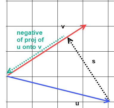
Figure 8. |
References and Auxiliary Resources:
- Linear Algebra Labs with MATLAB, Third Edition, by D. Hill and D. Zitarelli, 2004 Pearson Education, Section 10.2 (out of print; pdf file available at
Math Demos.org/books)
- An in dept discussion in Wikiapedia Dot Product
- Dot product and examples Dot examples
- Projections What is Projection Vector?
- Vector Algebra
============================
Go to MATH DEMOSDavid R. Hill